Forward Error Correction(FEC)
Introduction:
In modern communication systems, information is digitized, coded to logic levels “1” and “0” and often further encoded into complex modulation schemes such as Pulse Amplitude Modulation (PAM) or Quadrature Amplitude Modulation (QAM). Integrity of the information at the received end can be critical, so it is essential that any errors can be avoided, and if not, repaired.
When major errors occur in the transmitted data, such as where significant parts of the data is missing, or the frame looks very different from what is expected, Equipment Management Systems can determine a problem and manage it accordingly. But, minor errors, where only a small number of bits in the frame are corrupt, the data looks the same to the system and errors are therefore not so easily spotted. One single error can be enough to cause the meaning of the message to be drastically altered, but the system has no way of knowing it.
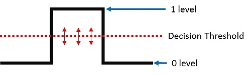
The diagram shows the voltage transition from logic “0” to logic “1”, then back to logic “0”. At a voltage level somewhere between the logic 0 and 1 state is a threshold, about which an electronic decision is made whether it should be a “0” or “1” at that point in the data stream. If the amplitude of the bit is not sufficiently above or below the threshold, an error in interpreting the data can result. Attenuation is the signal past, Jitter and Noise in the system can easily result in errors.
Parity Bits
Parity Bits provide one of the simplest ways to check if a received block of data has a bit error by counting the number of logic “1” and sending a parity bit along with the data.
Parity can be odd or even, but in this case let’s assume odd parity. If we send a data word 11101001 we count five 1s. Five being an odd number agrees with odd parity, so we allocate a “0” parity bit to follow the data. If the count of logic 1s had been even, disagreeing with odd parity, then we would allocate a “1” parity bit to follow the data.
At the receiver we simply apply the same calculation to the data word and check to see if the parity bit at the received end matches the parity bit sent.
Since bits are binary, having only two states, a single bit error will flip the parity bit from a “0” to “1” and vice versa. However, if two or any even number of errors occur in the word, the parity calculation cancels. So parity is only useful where errors are very unlikely, and, if they occur at all, only one bit is likely to be received in error. If the data is critical, the only course of action when parity fails is to have the data re-transmitted. It would be much more useful, when identifying an error, we had some way to correct it. FEC does exactly that.
Forward Error Correction
Forward Error Correction (FEC) is a process where the results of algorithms are sent as additional information along with the data from the transmit end. By repeating the same algorithms at the far end, the receiver has the ability to detect errors at the single bit level and correct them (correctable errors) without the need to have the data re-transmitted.
Hamming Code, probably the first form of FEC, was first invented by Richard Hamming as long ago as 1950. While working at Bell Laboratories, he was frustrated with frequent errors in the punch cards, used to record and transfer data at the time, so devised a coded method to identify and correct errors and so avoid the need to have the cards reproduced and resent.
Comments
Post a Comment