Optical Time Domain Reflectometer (OTDR)
Optical Time Domain Reflectometer (OTDR) |
The Optical Time Domain Reflectometer (OTDR) is useful for testing the integrity of fiber optic cables. It can verify splice loss, measure length and find faults. The OTDR is also commonly used to create a "picture" of fiber optic cable when it is newly installed. Later, comparisons can be made between the original trace and a second trace taken if problems arise. Analyzing the OTDR trace is always made easier by having documentation from the original trace that was created when the cable was installed.
OTDRs are most effective when testing long cables (more than aproximately 250 meters or 800 feet) or cable plants with splices. The data that the OTDR produces are typically used to create a picture called a "trace" or "signature" that has valuable information for the trained user and can be stored for later reference or to check against a blueprint when network trouble arises. OTDRs should not be used for measuring insertion loss in the fiber optic cable - that task is better left to a fiber optic test source and power meter. OTDRs simply show you where the cables are terminated and confirm the quality of the fibers, connections and splices. Of course, OTDR traces are also used for troubleshooting, since they can show where breaks are in fiber when traces are compared to installation documentation.
How Does an OTDR Work?
Unlike sources and power meters which measure the loss of the fiber optic cable plant directly, the OTDR works indirectly. The source and meter duplicate the transmitter and receiver of the fiber optic transmission link, so the measurement correlates well with actual system loss. The OTDR, however, uses a unique optical phenomena of fiber to indirectly measure loss.
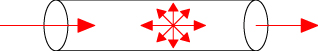
The biggest factor in optical fiber loss is scattering. In fiber, light is scattered in all directions, including some scattered back toward the source as shown here. The OTDR uses this "backscattered light" to make measurements along with reflected light from connectors or cleaved fiber ends.

The OTDR consists of a high power laser transmitter that sends a pulse of light down the fiber. Back-scattered light and reflected light returns to the OTDR through the fiber and is directed to a sensitive receiver thorugh a coupler in the OTDR front end. For each measurement, the OTDR sends out a very high power pulse and measures the light coming back over time. At any point in time, the light the OTDR sees is the light scattered from the pulse passing through a region of the fiber. Think of the OTDR pulse as being a "virtual source" created by the scattering that is testing all the fiber between itself and the OTDR as it moves down the fiber. Since it is possible to calibrate the speed of the pulse as it passes down the fiber from the index of refraction of the glass in the core of the fiber, the OTDR can correlate what it sees in backscattered light with an actual location in the fiber. Thus it can create a display of the amount of backscattered light at any point in the fiber along its length.
There are some calculations involved. Remember the light has to go out and come back, so you have to factor that into the time calculations, cutting the time in half. One must also cut the loss in half, since the light sees loss both ways. The power loss is a logarithmic function, so the power is measured and displayed in dB.
The amount of light scattered back to the OTDR is proportional to the backscatter of the fiber, peak power of the OTDR test pulse and the length of the pulse sent out. If you need more backscattered light to get good measurements, you can increase the pulse peak power or pulse width or send out more pulses and average the returned signals. All three are used in many OTDRs, with user control of some of the selections.
OTDRs are always used with a launch cable and may use a receive cable. The launch cable, sometimes also called a "pulse suppressor," allows the OTDR to settle down after the test pulse is sent into the fiber and provides a reference connector for the first connector on the cable under test to determine its loss. A receive cable may be used on the far end to allow measurements of the connector on the end of the cable under test also.

The OTDR picture (or "trace" as they are called) takes a lot of words to describe all the information in it! Consider the diagram of a trace at the right.
The slope of the fiber trace shows the attenuation coefficient of the fiber and is calibrated in dB/km by the OTDR. In order to measure fiber attenuation, you need a fairly long length of fiber with no distortions on either end from the OTDR resolution or overloading due to large reflections. If the fiber looks nonlinear at either end, especially near a reflective event like a connector, avoid that section when measuring loss.
Connectors and splices are called "events" in OTDR jargon. Both should show a loss, but connectors and mechanical splices will also show a reflective peak. The height of that peak will indicate the amount of reflection at the event, unless it is so large that it saturates the OTDR receiver. Then peak will have a flat top and tail on the far end, indicating the receiver was overloaded.
Sometimes, the loss of a good fusion splice will be too small to be seen by the OTDR. That's good for the system but can be confusing to the operator. It is very important to know the lengths of all fibers in the network, so you know where to look for events and won't get confused when unusual events show up (like ghosts, we'll describe below.)
Reflective pulses can show you the resolution of the OTDR. You cannot see two events closer than is allowed by the pulse width. Generally longer pulse widths are used to be able to see farther along the cable plant and narrower pulses are used when high resolution is needed, although it limits the distance the OTDR can see.
For details of OTDR Measurement refer below link: The FOA Reference For Fiber Optics - OTDRs
Comments
Post a Comment