Posts

ROADM

Image
  Network and bandwidth planning should be as easy as in SDH/SONET networks in the past. Within the given ring bandwidth, for example STM-16 or OC-48 each node could provide as much bandwidth as needed. Access to the entire bandwidth was possible at every ADM. Network extension, for example, introduction of a new node in an existing ring, was relatively easy and did not require any on-site visits of the existing nodes. The network diagram on the left illustrates this: Digital cross-connect systems link up with multiple optical SDH/SONET rings. Reconfigurable optical networks act differently: Bandwidth can be planned on-demand and the reach is optimized as the optical power is now managed per WDM channel. The scalability goes up significantly. The key element for enabling such a reconfigurable optical network is  Reconfigurable Optical Add-drop Multiplexer (ROADM) . It enables optical wavelengths to be redirected to client interfaces on just a click in the software. Other traff...


WSS(Wavelength Selective Switch)

Image
 What is WSS? W SS stands for Wavelength Selective Switch. WSS has become the central heart of modern DWDM reconfigurable Agile Optical Network (AOC). WSS can dynamically route, block and attenuate all DWDM wavelengths within a network node. The following figure shows WSS’s functionality. The above figure shows that a WSS consists of a single common optical port and N opposing multi-wavelength ports where each DWDM wavelength input from the common port can be switched (routed) to any one of the N multi-wavelength ports, independent of how all other wavelength channels are routed. This wavelength switching (routing) process can be dynamically changed through an electronic communication control interface on the WSS. So in essence, WSS switches DWDM channels or wavelengths. There is also variable attenuation mechanism in WSS for each wavelength. So, each wavelength can be independently attenuated for channel power control and equalization.   Reference: What Is Wavelength Selectiv...

Optical Time Domain Reflectometer (OTDR)

Image
  Optical Time Domain Reflectometer (OTDR) The Optical Time Domain Reflectometer (OTDR) is useful for testing the integrity of fiber optic cables. It can verify splice loss, measure length and find faults. The OTDR is also commonly used to create a "picture" of fiber optic cable when it is newly installed. Later, comparisons can be made between the original trace and a second trace taken if problems arise. Analyzing the OTDR trace is always made easier by having documentation from the original trace that was created when the cable was installed. OTDRs are most effective when testing long cables (more than aproximately 250 meters or 800 feet) or cable plants with splices. The data that the OTDR produces are typically used to create a picture called a "trace" or "signature" that has valuable information for the trained user and can be stored for later reference or to check against a blueprint when network trouble arises. OTDRs should not be used for measurin...

What is Super C-band

Image
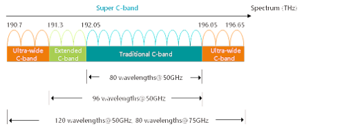
  Super C band uses the ultra-wide C band (C120) in addition to the traditional C band (C80) and the extended C band (C96). It increases the available wavelength range. Super C band can transmit 120 wavelengths at a 50 GHz channel spacing and transmit 80 wavelengths at a 75 GHz channel spacing, greatly expanding the effective working spectrum compared with the traditional C band and extended C band. Therefore, it is called Super C band. Benefits of Super C Band - Improving the system transmission capacity When the transmission rate is the same and the channel spacing is 50 GHz, the Super C band supports a maximum of 120 wavelengths, while the traditional C band supports a maximum of 80 wavelengths. The Super C band increases the transmission capacity by 50%. Refere for more details: Huawei-Super C Band

EDFA Optical Amplifier - Detailed reference

Image
 As an integrated part of long haul data transmission, an optical amplifier is able to amplify optical signals directly without the need to convert the signal into an electrical one before amplifying, which is also the most prominent feature. Among the many different optical amplifiers that can achieve amplification over long-haul optical communication, Erbium-doped fiber amplifier (EDFA) is one of the most commonly used types. EDFA Optical Amplifier—Boosting Optical Signals More Effectively When being transmitted over long distances, the optical signal has to be amplified many times in between owing to the signal loss from fiber attenuation, connectivity losses, fiber splicing losses, etc. Before an optical amplifier is invented, the optical signal has to be first converted into an electrical signal, amplified, and then converted back to an optical signal again. The process is very complicated and expensive. To overcome such a problem, the optical amplifier has...

EDFA vs RAMAN Differences

Image
 Raman amplifier performs better for two main reasons. Firstly, it has a wide band, while the band of EDFA is only from 1525 nm to 1565 nm and 1570 nm to 1610 nm. Secondly, it enables distributed amplification within the transmission fiber. As the transmission fiber is used as gain medium in the Raman amplifier, it can increase the length of spans between the amplifiers and regeneration sites. Except for the two advantages mentioned above, Raman amplifier can be also used to extend EDFA. However, if the Raman amplifier is a better option, why there are still so many users choosing the EDFA amplifiers? Compared with Raman amplifier, EDFA amplifier also features many advantages, such as, low cost, high pump power utilization, high energy conversion efficiency, good gain stability and high gain with little cross-talk. Here offers a table that shows the differences between EDFA and Raman optical amplifiers for your reference.  

Optical EDFA Amplifier Working principle

Image
  EDFA (Erbium-doped Fiber Amplifier), firstly invented in 1987 for commercial use, is the most deployed optical amplifier in the DWDM system that uses the Erbium-doped fiber as optical amplification medium to directly enhance the signals. It enables instantaneous amplification for signals with multiple wavelengths, basically within two bands. One is the Conventional, or C-band, approximately from 1525 nm to 1565 nm, and the other is the Long, or L-band, approximately from 1570 nm to 1610 nm. Meanwhile, it has two commonly used pumping bands, 980 nm and 1480 nm. The 980nm band has a higher absorption cross-section usually used in low-noise application, while 1480nm band has a lower but broader absorption cross-section that is generally used for higher power amplifiers. The following figure detailedly illustrates how the EDFA amplifier enhance the signals. When the EDFA amplifier works, it offers a pump laser with 980 nm or 1480 nm. Once the pump laser and the input s...